Guides / redraw pdf in cad
When to redraw a PDF in CAD instead of converting it
You should redraw a PDF in CAD when the file is a scan, when the scan is tilted, or when the drawing will be built from. Convert it when it is a vector PDF exported from a CAD program. That is the short answer, and we tested it: one A3 floor plan at 1:50, converted as a vector PDF and traced from four different scans, with every result measured in the DXF.
When is converting the better choice?
Convert whenever the PDF holds vector lines. Our test plan came out of the free PDF to DXF converter as 34 objects: 12 polylines, 14 lines and 8 text items on 3 layers, with the 10 000 mm outer wall within 0.001 mm once the scale was typed in. Redrawing that plan by hand means drawing the same 34 objects again, with a fresh chance of a typo in every one.
A vector conversion still needs a check. Hatching arrives as many short lines, symbols arrive as loose lines instead of blocks, and a plan with no stated scale needs one known dimension. Those are cleanup jobs measured in minutes, far below a full redraw.
When should you redraw instead?
Redraw when one of these is true:
- The PDF is a scan. A tracer follows both edges of every ink line, so each wall becomes an outline instead of a line, and text becomes letter shapes.
- The scan is tilted. A sheet fed 1.5 degrees off square gives walls that run 262 mm out over 10 m (about 3.1 in over a 10 ft wall). No scale setting fixes that.
- You need editable text. Room names, dimensions and notes come out of a trace as outlines. You retype them either way.
- The drawing is a base for new work. A survey you will build from, a part you will machine, a plan you will submit: anything with dimensions that matter should be clean geometry you drew yourself.
A traced scan is fine as a background: a site layout to sketch over, a reference for a quote, a check of room sizes to the nearest 100 mm.
What did the test show?
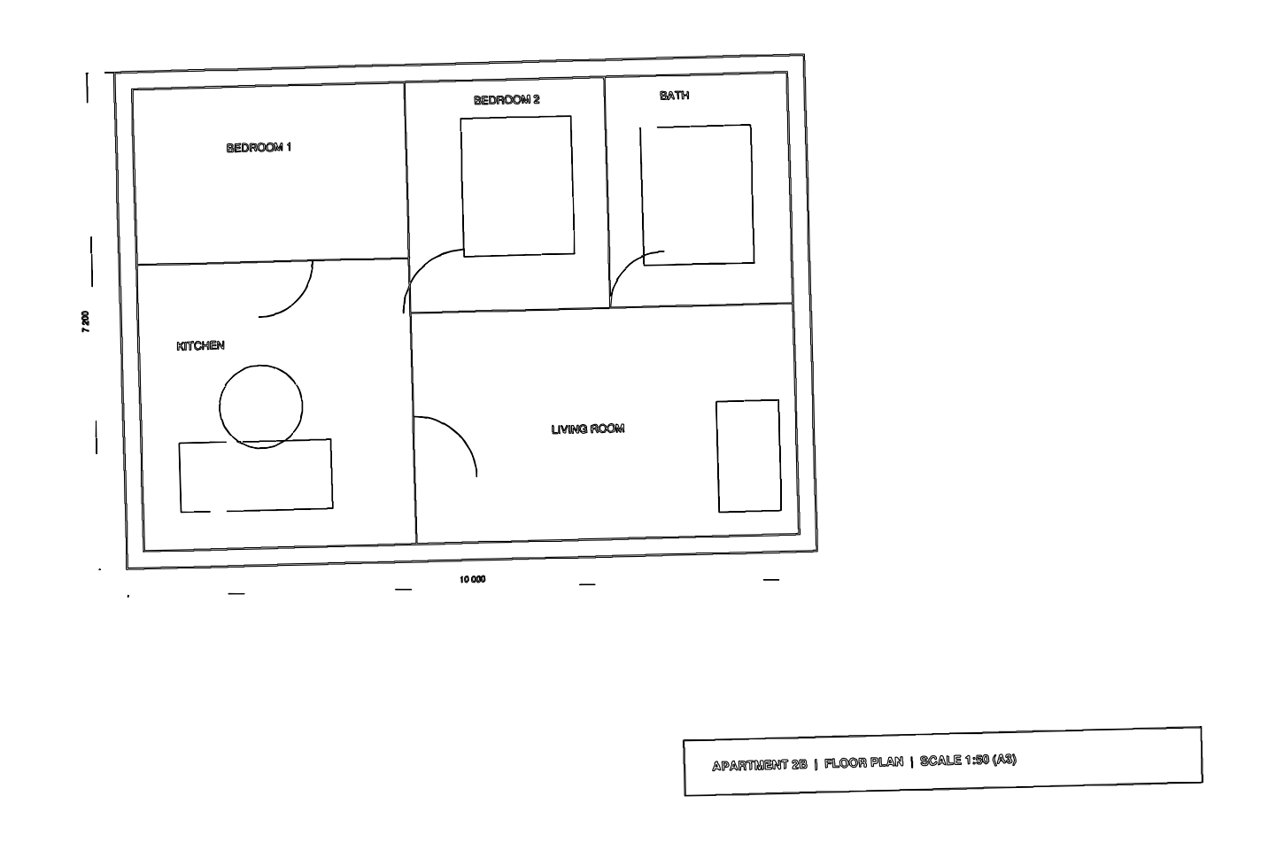
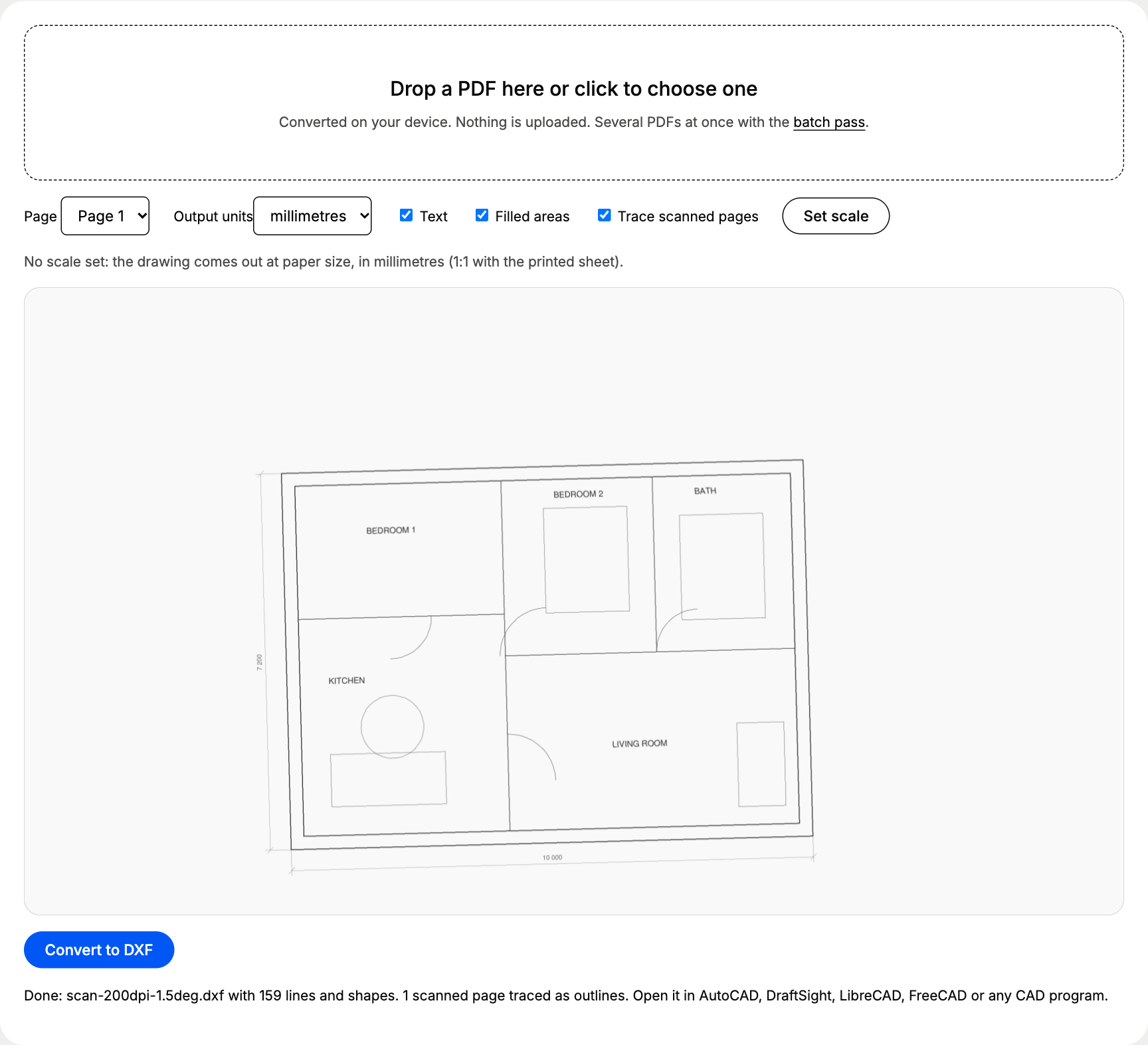
We made four scans of the same plan: 100, 200 and 300 dpi with a 0.4 degree tilt (a careful scan), and 200 dpi with a 1.5 degree tilt (a sheet fed in crooked). Each one went through the live converter with Trace scanned pages ticked, and each DXF was measured at 1:50 against the true 10 000 × 7 200 mm.
| Version of the plan | Objects | Points | Outer wall, mm | Text |
|---|---|---|---|---|
| Vector PDF, converted | 34 | 164 | 10 000 × 7 200 | 8 |
| Scan, 100 dpi, 0.4° tilt | 187 | 2 564 | 10 024 × 7 231 | 0 |
| Scan, 200 dpi, 0.4° tilt | 139 | 2 331 | 10 024 × 7 252 | 0 |
| Scan, 300 dpi, 0.4° tilt | 153 | 2 320 | 10 031 × 7 245 | 0 |
| Scan, 200 dpi, 1.5° tilt | 159 | 3 399 | 10 164 × 7 427 | 0 |
Two results surprised us. Resolution changed almost nothing: 100 dpi and 300 dpi traced to within 7 mm of each other on a 10 m wall. The tilt changed everything: at 1.5 degrees the outer wall alone broke into 179 short segments, 89 of them shorter than 50 mm, and the outline grew 3.2% taller because a tilted rectangle needs a bigger box.
Points in the DXF, same floor plan
| Vector PDF, converted | 164 |
|---|---|
| Scan, 300 dpi, 0.4° tilt | 2,320 |
| Scan, 200 dpi, 0.4° tilt | 2,331 |
| Scan, 100 dpi, 0.4° tilt | 2,564 |
| Scan, 200 dpi, 1.5° tilt | 3,399 |
Every traced wall also ran slightly off square: the long edges of the 0.4 degree scans sat 0.1 to 0.3 degrees off horizontal or vertical. Over a 10 m wall that is 17 to 52 mm, enough to break an Ortho snap and to make every room a few millimetres out of square.
How do you redraw a PDF in CAD?
A redraw goes quickest with the PDF scaled and squared underneath you. In AutoCAD or AutoCAD LT:
- Attach the PDF with PDFATTACH (a scan saved as JPG or PNG goes in with IMAGEATTACH). Put it on its own layer.
- Square and scale it in one step with ALIGN: pick both ends of a long known dimension as source points, draw a line of its printed length (10 000 mm in our test plan, or a length such as 32’-6” in an imperial plan) as the destination, and answer Yes to scaling. ALIGN uses the distance between the first and second points as the reference length, so the underlay comes out straight and at real size.
- Lock the underlay layer and turn Ortho on, so every wall you draw is truly square no matter how the scan leans.
- Draw from dimensions, never from the ink. Type the printed size (3 600, 2 400) for every wall and room; the underlay only shows you where things go.
- Retype text on a text layer, then measure two dimensions far apart before you save.
BricsCAD has the same PDFATTACH and ALIGN commands; in other programs, scale the underlay by reference and rotate it square before you draw. For a vector PDF you want to keep, the AutoCAD PDF import guide covers PDFIMPORT instead.
AutoCAD subscribers have one more option: the Raster Design toolset, included with an AutoCAD subscription, has vectorization tools that create lines and polylines from a scan. Treat its output like any trace and check it against the printed dimensions.
Can you convert first and redraw on top?
Yes, and for most scans that is the quickest plan. Trace the scan into a DXF, scale it, put it on a locked layer, and redraw over it. The trace gives you snap points near every corner, which beats an image underlay, and you replace its outlines with clean lines one room at a time.
Two details make this smoother:
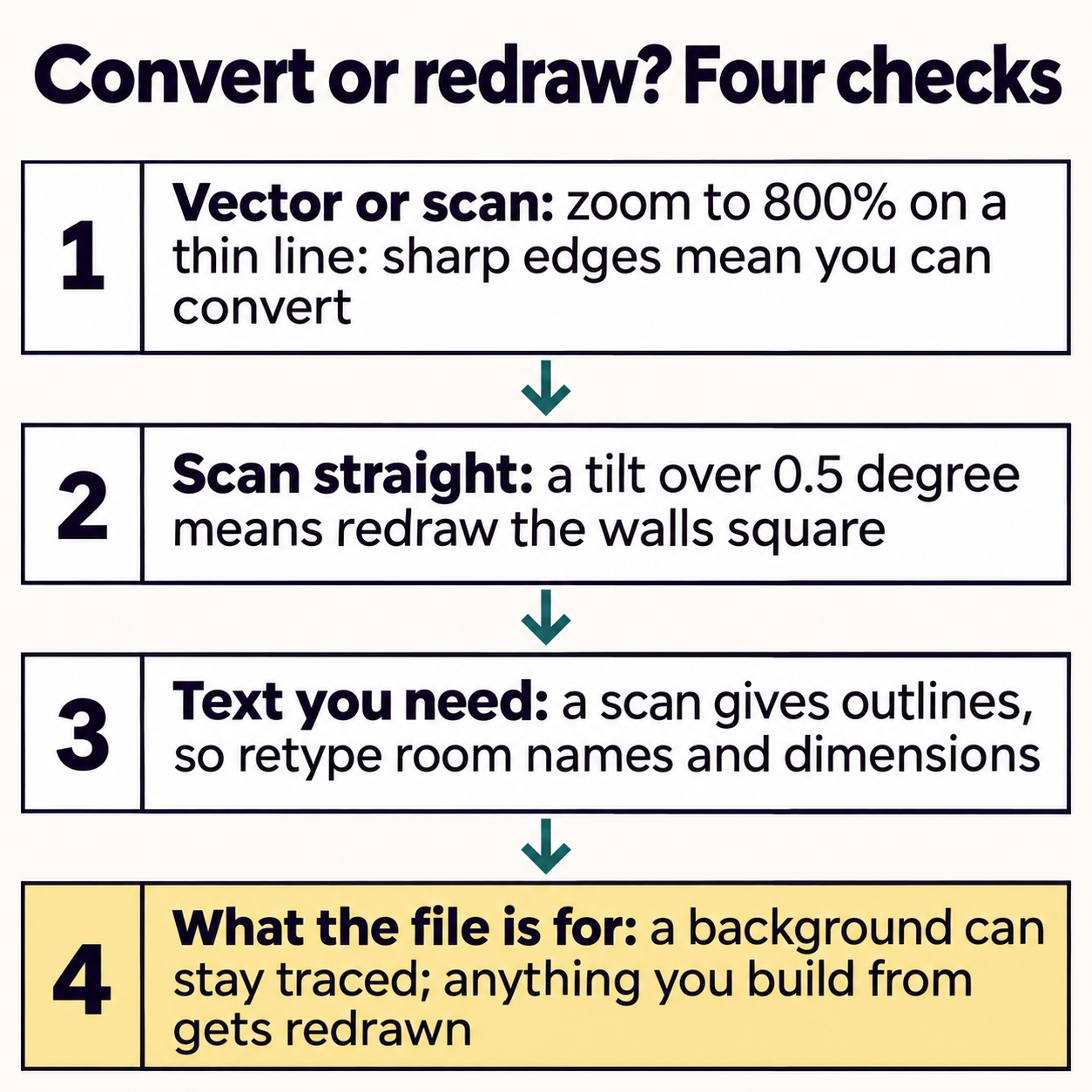
- Check the tilt first. Measure the angle of a long wall in the trace (DIST shows the angle in the XY plane). Under 0.5 degree, ALIGN or ROTATE squares the background well enough to snap near; at 1.5 degrees our trace broke the outer wall into 179 steps, so draw only from dimensions.
- Do not keep traced text. Letter outlines snap badly and look wrong in a title block. Delete them once the room names are retyped.
If you are unsure what kind of file you have, the vector or scanned PDF check takes 30 seconds, and the guide to a scanned drawing to CAD covers scan settings that keep the tilt down. When the check says vector, convert it with the free PDF to DXF converter and spend the saved hours on the drawing itself.
Questions people ask
Is it faster to redraw a PDF in CAD or to convert it?
For a vector PDF, converting wins: our test plan came out as 34 clean objects at the right size. For a tilted or poor scan, redrawing over a scaled underlay wins, because the trace gives you thousands of points to check and no editable text.
Does a higher scan resolution make a trace good enough to keep?
Not in our test. Scans at 100, 200 and 300 dpi traced to within 0.24 to 0.31% of the true width. A 1.5 degree tilt did far more damage than low resolution: 1.6% on the width and 3.2% on the height.
How do I redraw a PDF in AutoCAD?
Attach it with PDFATTACH (or IMAGEATTACH for a scan saved as an image), use ALIGN with Scale set to Yes on two points of a known dimension, then draw on your own layers with Ortho on and the underlay layer locked.
Can AutoCAD turn a scan into lines by itself?
The Raster Design toolset, included with an AutoCAD subscription, has vectorization tools that create lines and polylines from a raster image. The result still needs checking against the dimensions, the same as any trace.