Guides / pdf cad glossary
PDF and CAD terms glossary
This PDF CAD glossary explains the words you meet when you convert PDF to CAD: the PDF itself, the CAD file formats, the AutoCAD commands, scale and units, scans, and the language laser and CNC shops use. Each entry is two lines long and points to the guide that covers the subject in full. The numbers come from the handbook’s own test drawings, converted and measured on 2 November 2026.
Which words describe the PDF itself?
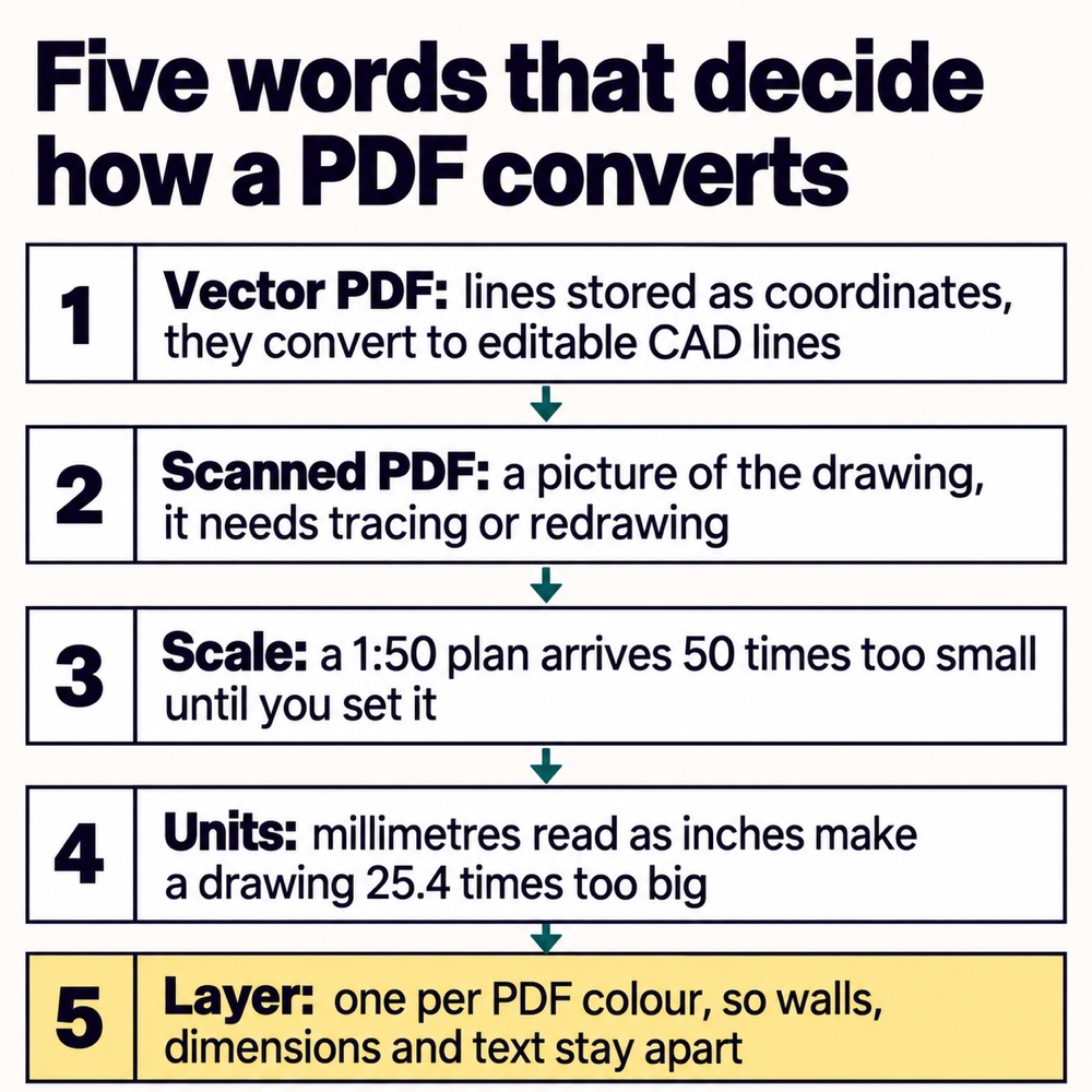
- Vector PDF: a PDF whose lines, curves and text are stored as coordinates. It converts into editable CAD lines; check yours with the 30-second vector or scanned test.
- Scanned PDF (raster PDF): a PDF holding a picture of the sheet, made of pixels. A converter has to trace the ink, and the result needs checking or redrawing from the scan.
- Hybrid PDF: vector lines on top of a scanned or photographed background, typical for marked-up plans. Only the vector part converts into clean lines.
- PDF point: the unit a PDF stores everything in, 1/72 of an inch or 0.3528 mm. An A3 sheet measures 1 190.55 x 841.89 points.
- Bézier curve: the only curve type a PDF knows, defined by four control points. A PDF has no true circle, so converters write curves as polylines or splines.
- PDF layers (optional content groups): layers saved inside the PDF by the program that exported it. AutoCAD’s PDFIMPORT can turn them into AutoCAD layers.
- Outlined text: text the exporting program turned into curves. It looks like text on screen and converts as letter shapes, with nothing left to edit.
- SHX text: text in AutoCAD’s own stroke fonts, stored in the PDF as short lines. AutoCAD 2018 and later rebuild it with PDFSHXTEXT, covered in the PDF to AutoCAD guide.
- Fit to page: a print setting that shrinks the sheet to the paper. The scale becomes a crooked ratio like 1:117, the classic reason a converted PDF is not to scale.
- Title block: the box with project, scale, paper size and revision. Read it before converting, because the scale and sheet size there give you the factor.
Which CAD file formats should you know?
- DXF (Drawing Exchange Format): Autodesk’s open format for exchanging drawings. Almost every CAD, CAM and laser program opens it.
- DXF R12: the AutoCAD Release 12 version (AC1009 in the file header). It has no LWPOLYLINE, no SPLINE and no units setting, which is exactly why every program reads it.
- DWG: AutoCAD’s own binary format. Save a DXF as DWG in any DWG-capable program, or follow the PDF to DWG without AutoCAD guide.
- ODA File Converter: a free tool from the Open Design Alliance. It converts DXF and DWG files between versions, a whole folder at a time.
- SVG: the vector format of the web and of many cutting machines. Inkscape and LightBurn read it, and FreeCAD imports it, as the PDF to FreeCAD guide shows.
- G-code: the line-by-line instructions a CNC machine runs. CAM software writes it from your DXF, see PDF to DXF for CNC.
What do the AutoCAD commands do?
- PDFIMPORT: in AutoCAD and AutoCAD LT 2017 and later. Turns PDF vectors, fills, TrueType text and raster images into AutoCAD objects.
- PDFATTACH: places a PDF as a linked underlay. You snap to it and draw over it while the PDF stays unchanged.
- Underlay: a referenced PDF, DWF or DGN shown inside a drawing without becoming part of it. A new revision replaces it by changing one path.
- PDFOSNAP: the system variable that lets object snaps find points on a PDF underlay. Value 1 (the default) means snapping is on.
- SCALE with Reference: scales objects so a length you pick becomes a length you type. The standard fix for a plan that arrived at paper size.
- OVERKILL: deletes duplicate and overlapping lines. Run it before a converted drawing goes to a laser.
- JOIN: merges lines and arcs whose ends touch into one polyline, so a CAM program sees one closed outline.
What are the parts of a DXF?
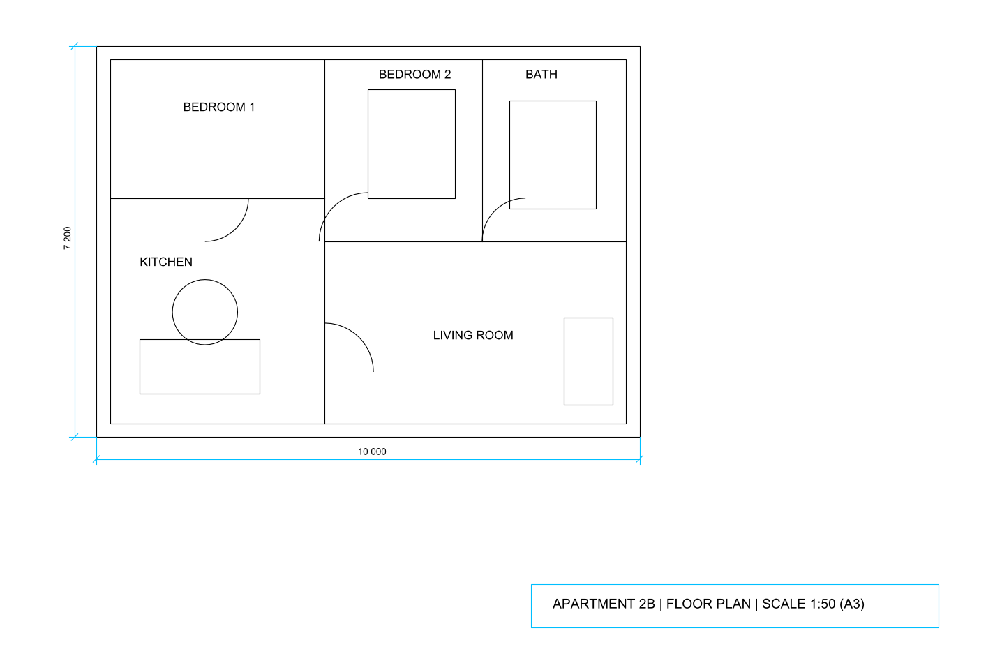
- Entity: one object in a DXF, such as a LINE, a POLYLINE or a TEXT. The A3 test floor plan converts into 34 entities, counted in the chart below.
- LINE: a straight segment between two points, the simplest entity of all.
- POLYLINE and LWPOLYLINE: a chain of connected segments, open or closed. R12 writes POLYLINE; LWPOLYLINE is the lighter form from R14 on.
- SPLINE: a smooth curve entity, added in R13. Some CAM and laser programs handle splines badly, which is why converters write curves as polylines.
- TEXT: one line of editable text with a height and a style. Room names arrive as TEXT when the PDF stored real text.
- Hatch: a fill pattern in CAD. A PDF has no hatch object, so hatching arrives as hundreds of separate lines.
- Layer: a named group of entities with its own colour and visibility. Converters split by PDF colour: PDF_000000 for black lines, PDF_TEXT for text.
- Block: a named group of entities placed many times, like a door or a chair. A PDF keeps no blocks, so doors arrive as loose lines.
- Model space and paper space: model space holds the drawing at real size, paper space the sheet layout. A converted PDF lands in model space at paper size.
Entities in the A3 test floor plan after conversion to DXF R12
| LINE | 14 |
|---|---|
| POLYLINE | 12 |
| TEXT | 8 |
Those 34 entities sit on three layers, one per PDF colour plus one for text:
Which words are about scale and units?
- Drawing scale: the ratio between paper and reality. At 1:50, the 10 m wall of the test plan is 200 mm on the A3 sheet.
- Scale factor: the number that brings a drawing to real size, 50 for a 1:50 plan. Measured on the test plan, factor 50 turns the 200 mm wall into 9 999.999 mm.
- Two-point scale: click both ends of a known dimension and type its real length. On the test plan this gave 9 996.4 mm, 0.036% off; see how to scale a PDF drawing.
- Drawing units: what one CAD unit stands for, a millimetre, an inch or a metre. A mismatch makes a drawing exactly 25.4 or 1 000 times off, explained in millimetres or inches.
- $INSUNITS: the DXF header value that names the units in newer DXF versions. R12 files have none, so you set the units when you open them.
- Calibrate: the Fusion 360 tool that sizes an attached canvas from two clicked points and a typed distance, covered in PDF to Fusion 360.
What happens to scanned drawings?
- Tracing (vectorization): turning pixels into lines. The converter on convertpdftocad.com traces both edges of the ink, so every wall becomes two outlines.
- Centre-line tracing: one line through the middle of each stroke. Closer to a CAD drawing, and the reason some drafters pay for dedicated raster-to-vector software.
- DPI (dots per inch): the scan resolution. At 300 dpi one pixel is 0.085 mm on paper, which is 4.2 mm on site for a 1:50 plan.
- Redrawing: drawing new CAD lines over a PDF or scan placed as an underlay. Slower than converting, and the dependable way to get clean walls from a scan: the traced test scan came out 38 mm long over 10 m.
What do laser and CNC shops mean?
- Closed path: an outline whose start and end meet. Lasers and CAM programs need closed paths, as the PDF to DXF for laser cutting guide explains.
- Duplicate lines: two lines lying on top of each other. The laser cuts the path twice and burns the edge.
- Kerf: the width of material the beam or bit removes. A router’s kerf equals the bit diameter; a laser’s is a fraction of a millimetre.
- Tolerance: how far a size may stray from nominal, such as ±0.1 mm. Measure converted holes against it before anything is cut.
- CAM (computer-aided manufacturing): software that turns a DXF into toolpaths and G-code for a machine.
- Toolpath: the path the cutter centre follows, offset by half the tool diameter from the line you drew.
Which programs open a PDF, and which need a DXF?
| Program | Reads PDF vectors itself | Opens DXF | Guide |
|---|---|---|---|
| AutoCAD and AutoCAD LT 2017+ | Yes, PDFIMPORT | Yes | PDF to AutoCAD |
| LibreCAD | No | Yes | PDF to LibreCAD |
| FreeCAD | No | Yes, File > Import | PDF to FreeCAD |
| SketchUp Pro | No (Mac imports PDF as an image) | Yes, DWG and DXF | PDF to SketchUp |
| Fusion 360 | No | Yes, Insert DXF | PDF to Fusion 360 |
| LightBurn | Yes, scans arrive as images | Yes | laser cutting |
| Inkscape | Yes | Saves DXF R14 | free methods |
When a term turns into a job, convert the PDF to DXF in your browser, set the scale on a known dimension and open the file with the guide for your program. Spotted a term that is missing? Tell us through the contact form.
Questions people ask
What is the difference between DXF and DWG?
DWG is AutoCAD's own binary format. DXF is the open exchange format that almost every CAD, CAM and laser program reads. Converters write DXF, and any DWG-capable program or the free ODA File Converter saves it as DWG.
What does vector PDF mean?
A vector PDF stores lines, curves and text as coordinates, the way a CAD program exported them. Zoom in to 800% on a corner: edges that stay sharp mean vector, edges that turn into squares mean a scan.
Why does a converted PDF arrive at the wrong size?
A PDF stores the printed sheet, so a 1:50 plan arrives 50 times too small. Set the scale from a known dimension before or after converting, and check the units match on import.
What is a PDF underlay in AutoCAD?
A PDF attached with PDFATTACH and shown in the drawing without becoming part of it. You snap to it and draw over it, and a new revision replaces it by changing one file path.